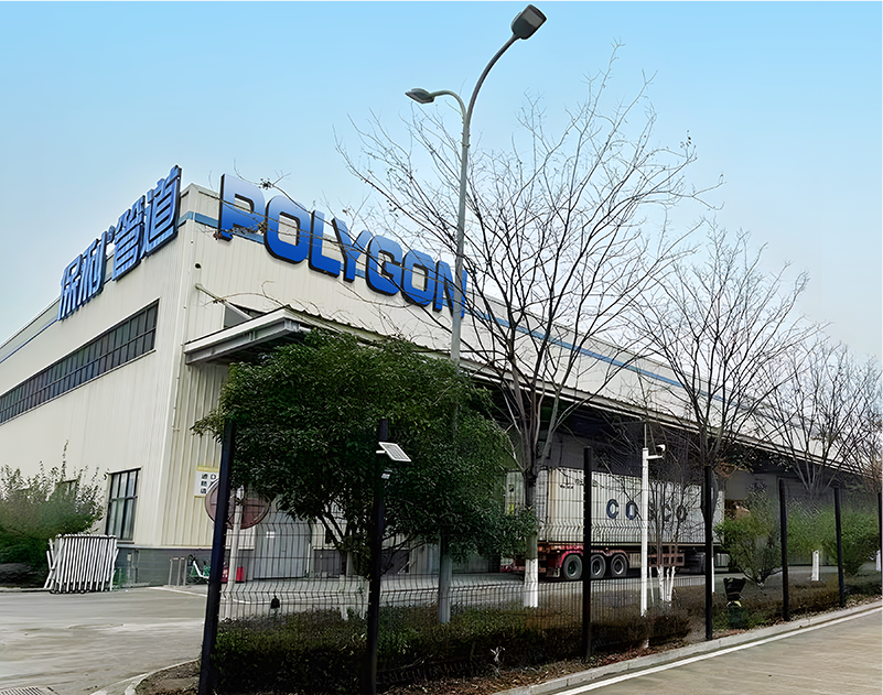

The construction quality of UPVC drain pipes directly determines the flow capacity, sound attenuation, and long-term sealing performance of the drainage system. The core of its process lies in utilizing solvent-weld socket (indoor) and rubber ring flexible (outdoor/buried) connections to build a stable gravity-flow network. The entire construction process must strictly comply with standards such as GB 50242 and CJJ/T 29, with a focus on five key aspects: connection, slope, support, compensation, and fire safety.
I. Pipe Connection: The "Standardized Six-Step Method" for Solvent-Weld Joints
Indoor UPVC drainage pipes mainly use solvent-weld socket connections, which are critical for leak prevention. Haphazard gluing is strictly prohibited; the standard procedure must be followed:
1. Cutting and Chamfering: Use a dedicated pipe cutter or fine-tooth saw for cutting, ensuring the cut is square and perpendicular to the pipe axis. Remove all internal and external burrs with a reamer or file. Chamfer the outer edge of the spigot end to 15°~30° to prevent damage to the cement layer or seal ring in the socket during insertion.
2. Test Fit and Marking: A test fit is essential before cementing. Insert the spigot into the socket to about 1/2~2/3 of the depth and check the fit. If satisfactory, mark the insertion depth on the spigot with a marker pen (standard insertion depth is typically 1/2~2/3 of the pipe diameter, e.g., ~25mm for DN50, ~50mm for DN110).
3. Cleaning and Degreasing: Thoroughly wipe the inner wall of the socket and the outer wall of the spigot within the marked area with clean cloth moistened with acetone or dedicated cleaner to remove grease, dust, and moisture. Moisture or contamination is a primary cause of joint failure.
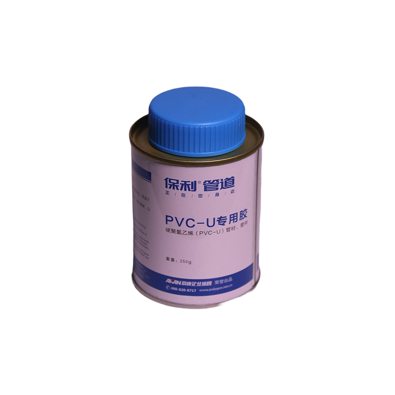
4. Applying Cement and Joining: Use dedicated UPVC solvent cement compatible with the pipe. Apply cement evenly and moderately, socket first, then spigot, ensuring a thin, uniform coat without gaps. Avoid excess to prevent cement from forming plugs inside the pipe. Immediately after cementing, align and insert the spigot with a twisting motion into the socket up to the mark, and hold under pressure for 30~60 seconds to prevent spring-back.
5. Curing and Settling: After joining, wipe off excess cement from the outside of the joint with a dry cloth dampened with cleaner. Allow the joint to cure undisturbed for 2~10 minutes (less in summer, more in winter) before handling or further installation. Avoid applying significant stress for 24 hours.
6. Rubber Ring Connection (Buried/Outdoor): For buried reinforced or large-diameter pipes, rubber ring connections are used. Before installation, check the O-ring for integrity and correct positioning. Apply soapy water as a lubricant during insertion to ensure full seating, creating a flexible seal adaptable to ground settlement.
II. Slope and Supports: The Physical Basis for "Water Flows Downhill"
As gravity-flow systems, the slope is the lifeline for UPVC pipes, and supports are the skeleton preventing sagging and deformation.
● Slope Control (Backfall Strictly Prohibited): Horizontal pipes must maintain the minimum design slope. Common standards are: DN50 ≥ 2.5%, DN75 ≥ 1.5%, DN110 ≥ 1.0%, DN160 ≥ 0.7%. Control during installation using a spirit level or laser level. Backfall, zero slope, or undulating profiles are strictly prohibited to prevent wastewater stagnation and sediment accumulation.
● Support Spacing (Preventing Sag): UPVC pipes have lower stiffness, requiring fixed and sliding supports as per code to prevent stress cracking at joints due to self-weight sag.
○ Vertical Stacks: Install a fixed clamp at each floor or every 1.5~2.0m (e.g., spacing ≤2.0m for DN110 stacks).
○ Horizontal Pipes: DN50 spacing ≤0.5m, DN75 ≤0.75m, DN110 ≤1.1m. Additional fixed supports are mandatory at bends, tees, and trap connections to resist water flow shock.
Component | Parameter / Requirement | Specification / Standard | Rationale / Consequence of Non-compliance |
Minimum Slope (Horizontal Pipes) | DN50 | ≥ 2.5% | Ensures self-cleansing velocity. Backfall causes stagnation, deposits, blockages. |
DN75 | ≥ 1.5% | ||
DN110 | ≥ 1.0% | ||
DN160 | ≥ 0.7% | ||
Support Spacing (Max.) | Vertical Stack | ≤ 2.0m (e.g., for DN110) | Prevents sagging, joint stress, and misalignment. |
Horizontal Pipe | DN50: 0.5m DN75: 0.75m DN110: 1.1m | ||
Mandatory Support Locations | Bends, tees, trap connections. | Add fixed support at these points. | Resists hydraulic thrust and water hammer forces. |
III. Thermal Expansion/Contraction and Fire Safety: The System's "Safety Valves"
UPVC has a high coefficient of linear thermal expansion and is a combustible material, necessitating compensation and protection measures.
1. Expansion Joint Installation (Compensating for Movement): Expansion joints must be installed as per design or code to accommodate thermal movement.
● Location: Install one per floor on vertical stacks (floor height ≤4m); for horizontal runs exceeding 2m in length, install near the stack connection.
● Gap: Leave a gap at the pipe end within the expansion joint: 5~10mm in summer, 15~20mm in winter to prevent thermal expansion damage.
● Direction: The expansion joint's socket must face the direction of water flow; reverse installation is strictly prohibited.
2. Firestop Collars and Fire Sleeves (Fire Safety Red Line): In high-rise buildings, exposed UPVC drain pipes (especially vertical stacks DN≥110mm) penetrating floors, firewalls, or pipe shaft walls must have firestop collars or fire sleeves installed below the penetration (under floor slab) or on both sides (within wall). The firestop collar should be flush against the underside of the floor slab, secured with expansion bolts, expanding to seal the opening in case of fire. Omission or retrofitting is strictly prohibited.
IV. Details for Vertical Stack and Horizontal Pipe Installation
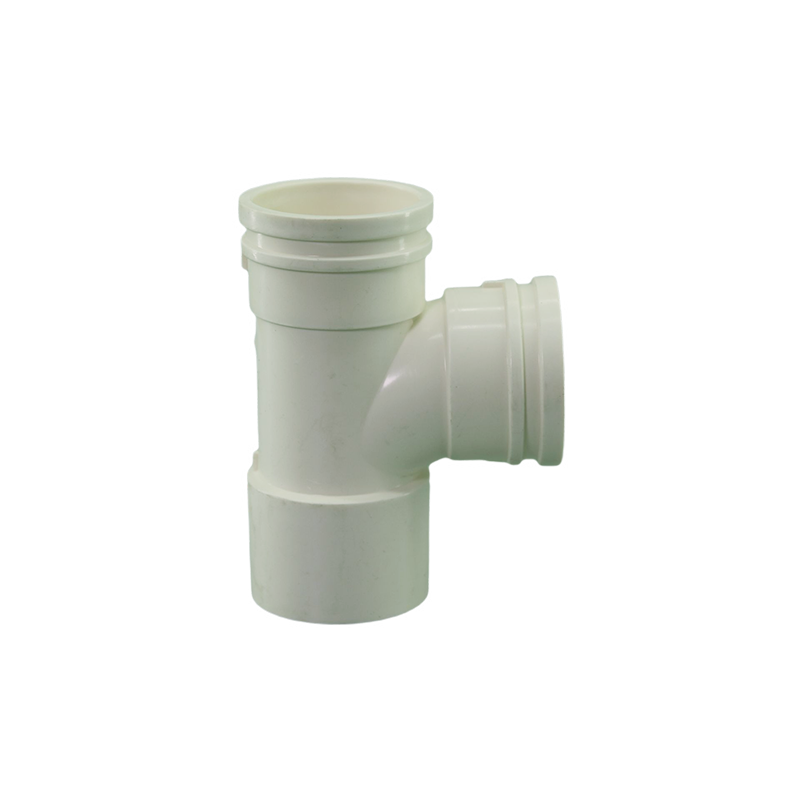
● Vertical Stack Alignment: Ensure vertical stacks are installed with a verticality deviation ≤3mm/m, aligning openings between floors. A 20~50mm offset from the wall is recommended for cladding and maintenance access.
● Access Fittings and Cleanouts: Install an access fitting on vertical stacks at every floor or alternate floors (center ~1.0m above floor). Install cleanouts at the end of long horizontal runs or where bends are ≥135° for future maintenance and rodding.
● Trap Seal: All sanitary fixtures (except toilets with built-in traps) must have a P-trap or S-trap installed on their drainage branch. The water seal depth must be at least 50mm, a non-negotiable requirement for preventing sewer gas ingress.
V. Product Protection and Water Testing
● Protection: After installation, protect pipe exteriors with plastic wrap to prevent contamination or scratches during finishing work. Never use UPVC pipes as scaffold supports or for hanging heavy objects.
● Water Flow Test: Upon system completion, a water flow test is mandatory (fill to the level of the lowest fixture's flood rim). The system passes if joints are leak-free and drainage is unobstructed.
Summary
The essence of UPVC drain pipe installation lies in "precise connection + accurate slope + rigid support + flexible compensation". Installers must treat each solvent-weld joint with surgical precision and strictly control the placement of expansion joints and firestop collars. This transforms the material advantages of UPVC into a reliable, leak-free, low-noise, and long-lasting drainage system.
Related Articles
CONTACT
Get in Touch With Us